Sunday 5 July 2015

CNC Plasma update

It has come to me that I have not updated the blog for ages. So apologies to all who are reading, I also hate when I get to a blog and the author has just stopped for no explanation. Guilty ;)

So much has happened since I last wrote in the blog. 1 change in shift roster (which was a complete waste of my time) and a consequent change in jobs, getting married etc etc....... It is almost complete! So I quick run down in points since October last year, how do I condense so much work into one blog post????

  • Y axis bearings and rails installed
  • Z axis mount machined and mounted to bearings
  • I manufactured a floating torch mount, but its pretty crap. More on that later.
  • All rack and pinion gear mounted
  • 3:1 gear reduction assemblies made up
  • All drive shafts drilled and pinned due to the massive amount of torque causing the 2mm grub screws to come loose all the time.
  • Electronics were ordered and delivered
  • Limit switches installed
  • All wiring was finished and cleaned up
  • Wiring management sorted out with cable trays
  • Water tray frame was fabricated and installed
  • Water tray bent up and welded - still to see if it has any leaks.........
  • Supporting slats installed. This will be modified as I have the money
  • Made up and mounted some wheels to it to be able to at least move the behemoth. They are not very pretty but they do the job for the mean time.
  • Test runs!
  • More test runs.
  • Found a myriad of problems with it.
  • Fixed problems.
  • Some more testing
  • Fixing..........
  • I moved the whole machine to South Windsor which is over an hour closer to home so I can work on it on the weekends and have things happening.
Anyway, enough of the point rambling. I wish I had some more time to delve into the problems and solutions that I came up with but I think I would be writing this for at least a day. So without further waffling, here is some pictures. Hopefully in some semblance of order.


Friday 31 October 2014

Table gantry and parts coming

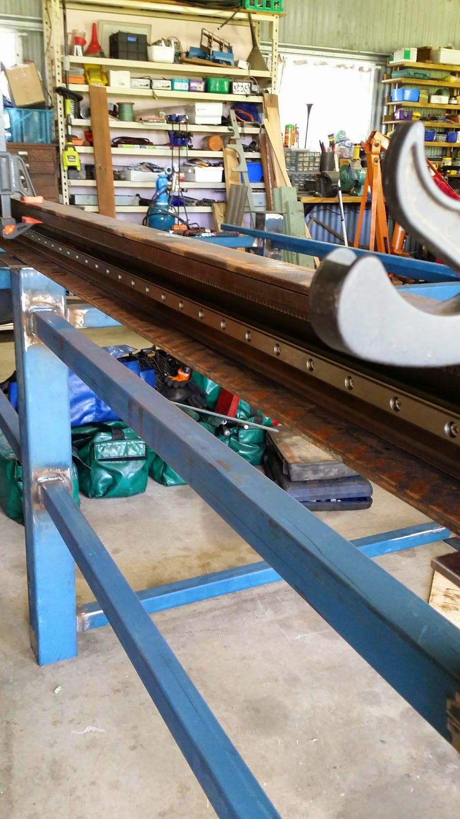
This week has seen a bit of work and some milestones achieved. I was going to buy a rotating laser level to get the gantry rails all levelled out and had a brain wave that a mate had a laser level already. And he did, so I got away with being able to spend another $500 on the table instead of a leveller. Happy days!! So the laser level worked brilliantly and the gantry side rails are now level. The left hand was slightly higher than the right so I had to raise it up using slim packing strips. I think one of the gaps is 4mm and lower from there. I've got some steel and I'll pack that in and weld the side into place. I wasn't going to weld them in, but it's the easiest way to go at the moment.

I had 2 6mm plates water jet cut for the uprights of the gantry. It may be a bit heavy but the more I think about it the more I think it would be about the same weight as the aluminium I would have used. Also it is about a tenth of the work and headache. I have used 100 x 100 x 3mm RHS as the gantry cross member. I think this is too heavy but it was the only thing that was 100 x 100 that was cheap and easy to work with. No matter, I will be making some weight saving cuts to the bottom of it to be able to get my hand in there to bolt the linear bearings in place.


On that note, I have changed the design. I was going to use 2 x SBR16 rails with 4 bearings but the bearings have taken 3 weeks and still no luck with getting delivery and because of the delay I have over thought it and then made a better design decision. I am going to use 2 x HGR15 rails with 2 bearings on the top rail and one on the bottom. The rails are pretty small but the load shouldn't be all that much compared to the x axis having to hold up the gantry and the z axis head. The parts have been marked as shipped today so I'll have them all next week.

I had a guy at work machine up the spacer blocks for the uprights. He is actually a fitter and turner by trade as opposed to a mechanic hack like myself. They came out pretty spiffy. We used the marking out table and vernier height gauge to mark out the mounting holes and I took them home to drill. What I got wrong was that I drilled the holes in the first 2 blocks at exactly 6mm and the bolts are 6mm. This caused the rear bearing block on the left to be slightly crooked and caused 4 of the ball bearings to be forced out. I saved them all and got all but one back in. I still have it safe, so I will have to pull that bearing block apart and get it complete again. I then changed to a 7mm drill and did the other blocks. Perfect. I have 1 bolt on the other side that just does not want to go home. I think this machinist hack got a bolt hole slightly wrong.


I think the gantry isn't as smooth as I expected. It still moves pretty good and doesn't need too much force to get it moving. I still haven't filled the bearing blocks with grease yet. So hopefully its a combination of lack of lubrication and the blocks being brand new. It is however square and flat. There is a possibility that there is a little bit of twist when only one side is pushed. I'll have to weld it all together and work out if it needs a stiffening plate on the uprights. It will have a stepped and reduction drive on either side though which will also keep it running true.


It's my first time building this and I'm sure that there are things I have done which are not correct and possibly appear stupid. The fact is this - I'm doing it. If there is any arm chair critics out there who have never attempted to give this a go and desire to tell me I'm wrong i'll listen, but whether i'll take notice is another matter. Just one or two people who I know have never even thought about it have given me advice on things which pisses me off.

On the other hand, I would like to take this opportunity to thank all the guys on the Plasmaspider forum who have helped out with constructive feedback, ideas and information. It has been such a good resource for me, and has helped a great deal in making this build happen.

Monday 29 September 2014

Mock up of x axis

I finished the second x axis rail installation tonight and got it onto the table to mock up a position that they will be mounted. I checked the straightness of the rail mounting to the back of the c channel and I'm 1 degree out over the length only one and .8 degrees out on the other over the length. Not too bad, also Ok because the difference in angles is almost exactly mirroring each other. I have decided to move the c channel further over one end of the table so I can put some short extending rails at the end of the main and be able to park the gantry clear of unloading and loading of sheets. Will see how this goes later on.

Major issue is still getting both rails at exactly the right height and distance apart. I think I'm going to have to make up a jig on a sheet of braced ply that will hold the two channels into place and then weld the channels into place. Getting everything perfectly level will then be a matter of installing some levelling feet to the table. Back to the sketch books to come up with ideas for the jig.

Y axis gantry

Just figuring out the y axis gantry at the moment. What linear bearings, what do I make the gantry bridge out of, what height do I need it etc. I have worked out that I need to have the supporting bearings closer together than I first thought due to if I have them wide I'll lose half that width due to the length of the rail and where the torch is positioned. With the x rails being 3000 mm long, I should have at least 2600 in table travel. Hopefully more but as long as it will fit a 2400 X 1200 sheet of material.

I have been thinking also of buying some shorter rails and extending the table to make a drum and cylindrical cutter assembly on the end. Basically have a 44 gallon drum on rollers controlled by the x axis that will turn the drum and the y axis gantry just doing its thing. Ideally I'll also have a rotary tube cutter as well, but that is a bit away.

Wednesday 24 September 2014

Plasma table part 2

Over the past 2 days I have continued with the plasma table build.  The x axis rails are made using a 120x65x6mm C section steel lintel, usually reserved for construction sites. I've used this because where the main x axis linear bearings sit, the C section gives protection from whatever Flys off the water table or any slap that may come off. It also protects the very expensive rails from having stuff dropped on it. This C also provides a surface to mount the fairly huge Mod 2.0 gear rack and again its protected and pointing downwards so nothing gets into the teeth of the rack. So the design will help greatly to keep the major moving areas clean and undamaged.

The two sections housing the rack and rails are fucking heavy by the way. These needed to be drilled 40mm up from the bottom with 50 6 mm holes to fit the linear bearing to it. Both had to be exactly the same as each other, so I turned them back to back making an even heavier i beam (couldn't find an i that looked like a beam) tack welded them together and then set about milling up a drilling jig out of aircraft grade alloy billet I had acquired from somewhere. Probably $100 of alloy used to make a jig but it was free so I felt not so bad.

My Dad is an engineer and he had this idea to use the pedestal drill and a long series drill bit. So I took his idea and ran with it. I made a whole jig, made slides and a work table out of scrap rhs lying around and attempted the first hole. Dismal dismal failure. In no way was the massively heavy pedestal drill (I can just lift it) going to keep perfectly still on the sliding jig set up.

I went back to my idea which I had drawn out on BobCad weeks in advance. Grabbed more of that amazing aircraft alloy and made a drill guide jig. With the jig in place and the linear rail held in position, I drilled the first, middle and last hole perfectly using vernier and whatever other measuring stuff I could find. Bolts were fitted and tightened and then I drilled the holes in the center of where the bolts were now. This made it secure and as far as I could tell (with the help of yet another bit of brilliantly milled alloy ;)) were exactly correct. The holes are 7mm and the bolts are 6 mm but that gives me some room to move things very slightly if I need to to get it more correct when dialing in the table once finished.

All 50 holes were drilled and it took me ages. Cleaned up the scarf and had one of those "Fuck yeah, I'm pleased with myself" moments. I split the I beam and checked everything yet again. Still pleased with myself. I demurred all the holes with a larger drill bit and then put the rail back on using my billet guage to help with the alignment. After getting RSI from doing fitting up 50 M6 bolts, washers, spring washers and nylocks it turned out absolutely mint. See pictures below. Can't wait to get the other side done in a week or so.

Tuesday 23 September 2014

Project continuation

Hi all, if there is anyone still reading this blog. Anyway, that's not entirely why the blog is here. It's my outlet to get ideas onto paper, well, into words on a screen anyway. Since my last update I have finally moved back to Sydney! I've been a bit quiet on the Clubman build regardless due to getting a job which turned out I hated with an absolute passion, and a positive is that I have started designing and building my own CNC plasma cutter.

Since I last blogged about the plasma cutter idea I decided that to spend $18k on a turn key table was way too over the top especially as i didn't get made redundant from the previous job. So I have designed and built my own table and have started the design and build of the CNC axis. The table has a cutting envelope of 3000 x 1500mm, well slightly less due to the size of the gantry on the X and Y rails. Anyway, about to go up to the folks for a day and a bit of working on the table x axis. Can't wait. I'll leave with a few pictures.


Monday 9 December 2013

Start of registration VSCCS procedure

www.rms.nsw.gov.au/registration/downloads/vsccs_brochure.pdf